

Start with all-up mass including the battery and payload. Use propeller diameter and tip clearance to find the minimum layout dimensions, then check disk loading and the space needed to mount the actual components.
1. Add up the complete takeoff mass
Include the frame, motors, propellers, ESCs, battery, electronics, wiring and payload in the calculator’s weight input. The following hypothetical component budget illustrates the sum.
| Assembly | Total mass |
|---|---|
| Frame, landing gear and fasteners | 500 g |
| Four motors, propellers and ESCs | 400 g |
| Battery | 600 g |
| Flight controller, radio and wiring | 200 g |
| Payload and mount | 300 g |
| Total | 2,000 g = 2.0 kg |
Mark unselected components as estimates and replace them with actual masses when parts are chosen. Avoid counting a component in more than one assembly.
2. Derive the minimum dimensions from tip clearance
For four motors at the corners of a square, with equal-diameter propellers rotating in the same plane, adjacent motor centers must be separated by at least propeller diameter D plus tip clearance c.
Minimum frame diagonal F = √2 × (D + c). A 10-inch propeller is 254 mm across. With an assumed 15 mm clearance, √2 × (254 + 15) gives about 380.4 mm. This diagonal joins opposite motor centers; it is not the aircraft’s outside dimension.
The calculator’s general expression is F = (D + c) ÷ sin(π/n). It gives the diameter of the circle containing n equally spaced motor centers. For three motors, this is not an actual motor-to-motor distance. The expression does not directly describe asymmetric frames or coaxial rotor layouts.
| Propeller diameter | Adjacent motor spacing | Minimum diagonal |
|---|---|---|
| 8 in (203.2 mm) | 218.2 mm | 308.6 mm |
| 10 in (254.0 mm) | 269.0 mm | 380.4 mm |
| 12 in (304.8 mm) | 319.8 mm | 452.3 mm |
15 mm is the calculator’s Standard-mode setting, not a universal clearance requirement. Account for blade and arm deflection, assembly tolerances and clearance to the body, wiring and payload.
Explore rotor placement and wakes
After sizing the frame and propeller clearance, explore the airframe, rotor layout and wakes in a quadcopter visualization sample.
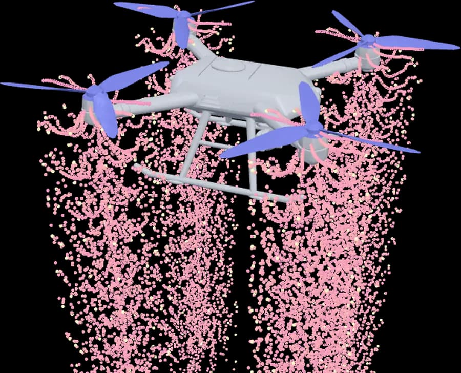
Toggle the body, rotor lattice and wakes to explore the 3D view.
3. Compare disk loading at the same mass
For n equal, non-overlapping rotors, total swept area is A = n × π × (D/2)², with D in meters. In level hover, disk loading is aircraft weight divided by this area: mg/A. This calculator uses g = 9.81 m/s².
At 2 kg with four 10-inch rotors, total area is about 0.2027 m² and disk loading is 2 × 9.81 ÷ 0.2027 ≈ 96.8 N/m². The kg/m² display is mass divided by area.
| Propeller diameter | Total rotor area | Disk loading |
|---|---|---|
| 8 in | 0.1297 m² | 151.3 N/m² |
| 10 in | 0.2027 m² | 96.8 N/m² |
| 12 in | 0.2919 m² | 67.2 N/m² |
This comparison holds mass constant. Recalculate if larger rotors require heavier motors or a heavier frame. Low disk loading alone does not establish power consumption, noise or flight capability.
4. Check component fit, then select the motors
Use candidate frame drawings to check motor centers and mounting space after calculating the minimum geometry. A marketed frame class alone does not establish propeller fit.
- Check propeller swept volumes against arms, center plates, cameras and wiring.
- Check motor mounting holes, battery retention space, payload position and center of gravity.
- Assess arm and joint stiffness, vibration and loads separately. Clearance geometry does not calculate structural strength.
- Update all-up mass using the selected frame, battery and motors, then compare required thrust with propulsion test data.
Questions and answers
Why does changing weight leave the minimum frame size unchanged?
The calculator derives minimum geometry from propeller diameter, clearance and motor count. Weight changes disk loading. If the increased weight leads you to select larger propellers, the required frame dimensions change too.
Can I use any frame larger than the calculated size?
First check whether its quoted dimension is the opposite-motor diagonal of a square layout. Body and payload clearance, mounting holes, stiffness and center of gravity remain separate requirements. Frame classes and disk-loading bands in the calculator are comparison references.